This article studies selected portions of the unit schematics, with particular focus on intermittent mode operation and the coordination between the bleed solenoid and dump solenoid to ensure patient safety. This blog serves as pedagogical material for understanding circuit operation and for developing structured troubleshooting strategies for Biomedical Equipment Technicians (BMETs).
We begin with the intended clinical usage of the unit, followed by a discussion of its general functional architecture and mechanical components. The system is then decomposed into block-level subsystems, with inputs and outputs identified in relation to the device’s operational requirements.
Through schematic-level analysis, the goal is to localize faults to smaller functional units, thereby reducing unnecessary replacement of expensive assemblies and promoting efficient repair practices.
Finally, several troubleshooting scenarios are presented along with practical diagnostic strategies.
Unit Description
The Impact 326/326M is a self-contained, portable medical suction (aspirator) unit designed to remove bodily fluids such as airway secretions, blood, wound drainage, or other debris during clinical and emergency procedures. It incorporates a vacuum pump, control circuitry, and collection system in a compact, lightweight housing suitable for ambulances, field use, emergency rooms, and transport environments. ( Citation: , 2007 (2007). Ultra-lite model 326 intermittent aspirator. Retrieved from https://respiratory-therapy.com/miscellaneous/ultra-litetrade-model-326-intermittent-aspirator/?utm_source=chatgpt.com )
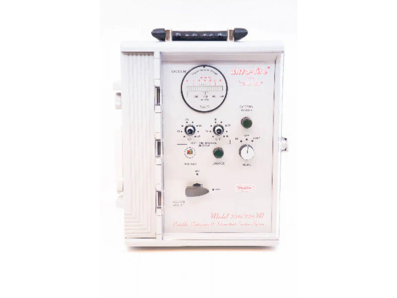
The USAF requires the Zoll 330M suction asporators to replace the current Zoll 326M. The original equipment manufacturer (Zoll) has issued an End of Service Life memorandum for the 326M Suction Aspirator. Despite being outdated, it contains a barebone design of an analog medical device that still serve a pedagogical purpose and provide insight to troubleshooting medical equipment device font-end.
General function
The most notable feature of 326M is a Flexible suction modes. It Offers both continuous suction (steady vacuum up to approximately 550 mmHg) and programmable intermittent suction (vacuum pulses up to about 200 mmHg) to accommodate different clinical needs.
And it also contains two safety mechanism to bleed excessive pressure from the vaccum pump as well as dumping the pressure as soon as the pump is OFF to ensure safe operation on the patient.
The unit is supported by two Power options; it can operate on mains AC power, vehicle DC power (e.g., 12 V from an ambulance), or its internal rechargeable battery, allowing several hours of use during transport or backup situations. It has a specific circuit mechanism to switch between inlet power input and the battery input and a battery charging mechanism.
Basic Components
The vacuum pump converts electrical energy into pneumatic suction, generating negative pressure to transport fluid into the collection canister. In intermittent mode, the pump is periodically switched ON and OFF according to user-defined timing parameters.
When vacuum builds during operation, mechanical inertia and pneumatic dynamics may cause pressure overshoot. To prevent unsafe vacuum levels:
The bleed solenoid provides controlled venting of excess negative pressure. It opens when regulation is required, acting as a fine-adjustment mechanism during pump operation.
The dump solenoid rapidly equalizes pressure when the pump transitions to its OFF state. It opens briefly to release vacuum and ensure immediate cessation of suction at the patient interface.
Mode of operations.
- Continuous
In continuous mode, the vacuum pump operates steadily until manually stopped. Pressure is regulated through the bleed solenoid.
- Intermittent mode
The intermittent cycle proceeds as follows:
- Pump ON phase — vacuum builds. Bleed solenoid regulates pressure.
- Pump OFF transition — dump solenoid energizes.
- Pressure equalization.
- Cycle repeats.
During vacuum build-up, both solenoids remain inactive. When the pump switches OFF, the dump solenoid opens for a preset duration to equalize pressure.
Schematics Analysis
From functional analysis, the intermittent operation requires:
- A timing circuit defining ON and OFF durations.
- Logic circuitry coordinating bleed solenoid and dump solenoid state based on pump states.
- A stable and efficient voltage source for pump drive.
System Architecture
A simplified block diagram is reproduced in LTspice.
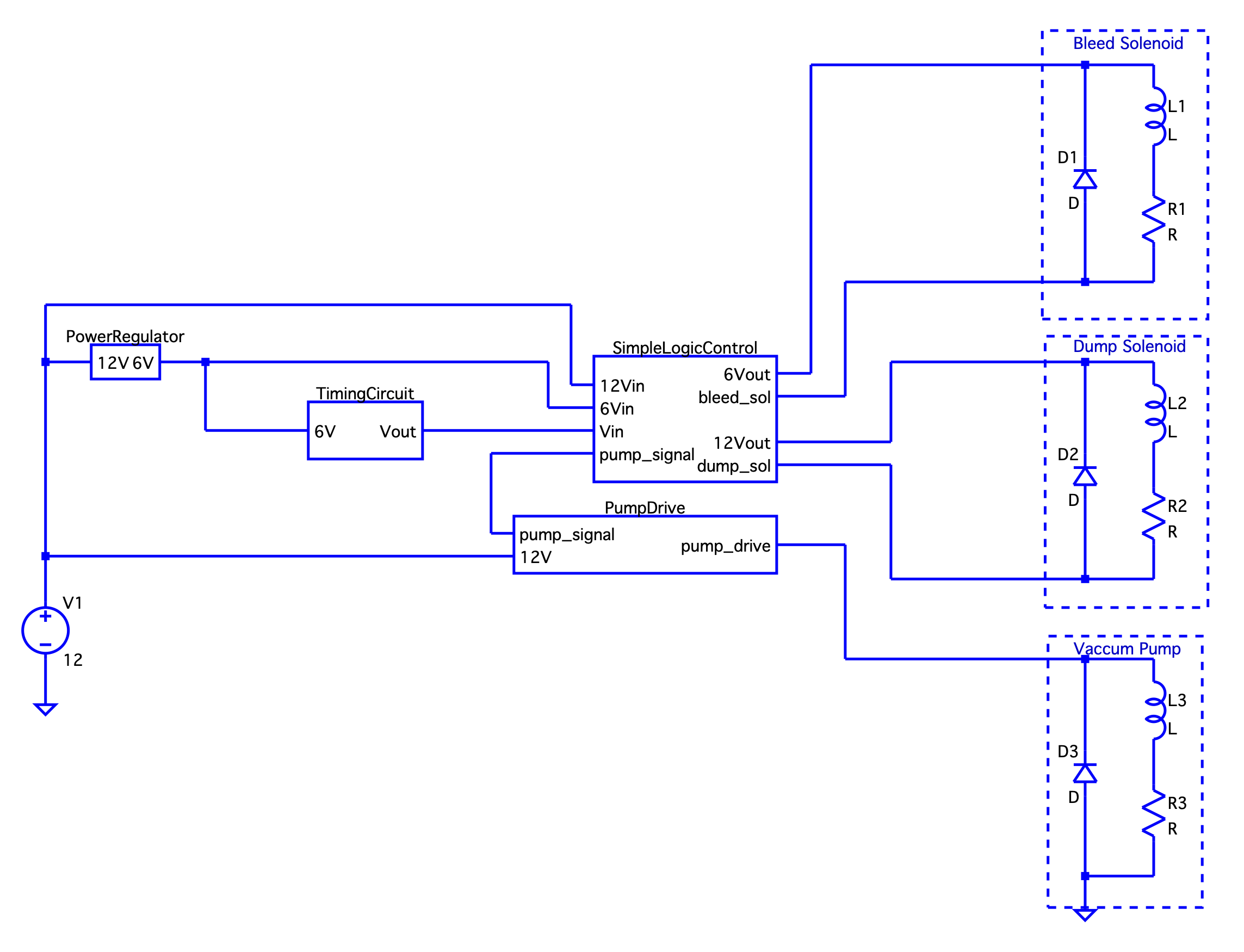
Simplify version of schematics to demonstrate the intermittent operation mode.
From left to right, starting with the power supply: The 12 V supply feeds the PowerRegulator, the SimpleLogicControl and the PumpDrive.
The PowerRegulator generates a stable 6 V supply for SimpleLogicControl and the TimingCircuit.
The TimingCircuit produces a square wave with durations \(\tau_{ON}\) and \(\tau_{OFF}\) preset by the user. The SimpleLogicControl sense the square wave and coordinates the bleed solenoid, dump solenoid, and pump drive according to the timing state.
The PumpDrive takes in the pump signal from SimpleLogicControl and converts the 12 V unregulated input into a regulated 6 V stable output using a switching voltage regulator.
Timing Circuit
The timing circuit consist of three major subcircuits that account for three mechanism. Starting with the set of NOR gates on the top left corner. They are generate a self-oscillating square wave. The capacitor then turns the square wave into spikes to trigge the top NE555 monostable that controls the duration of the OFF state of the pump signal\(\tau_{OFF}\). The bottom NE555 monostable vice versa controls the On state of the pump signal \(\tau_{ON}\). The duration is set by the value of the variable resistor set \(R_{1}, R_{2}, R_{3}\) and \(R_{8}, R_{9}, R_{10}\).
The TimingCircuit then does the following: taking in a \(6V\) input to produce a squre wave with a high of \(6V\) and \(0V\) with the a preset duration based on the time constant varies from the resistor value \(\tau = CR\). For a detail discussion of the NE555 timing circuit, the following blog page gives an elaborated overview:
( Citation: Shirriff, 2016 Shirriff, K.(2016, 2/20). Retrieved from https://www.righto.com/2016/02/555-timer-teardown-inside-worlds-most.html )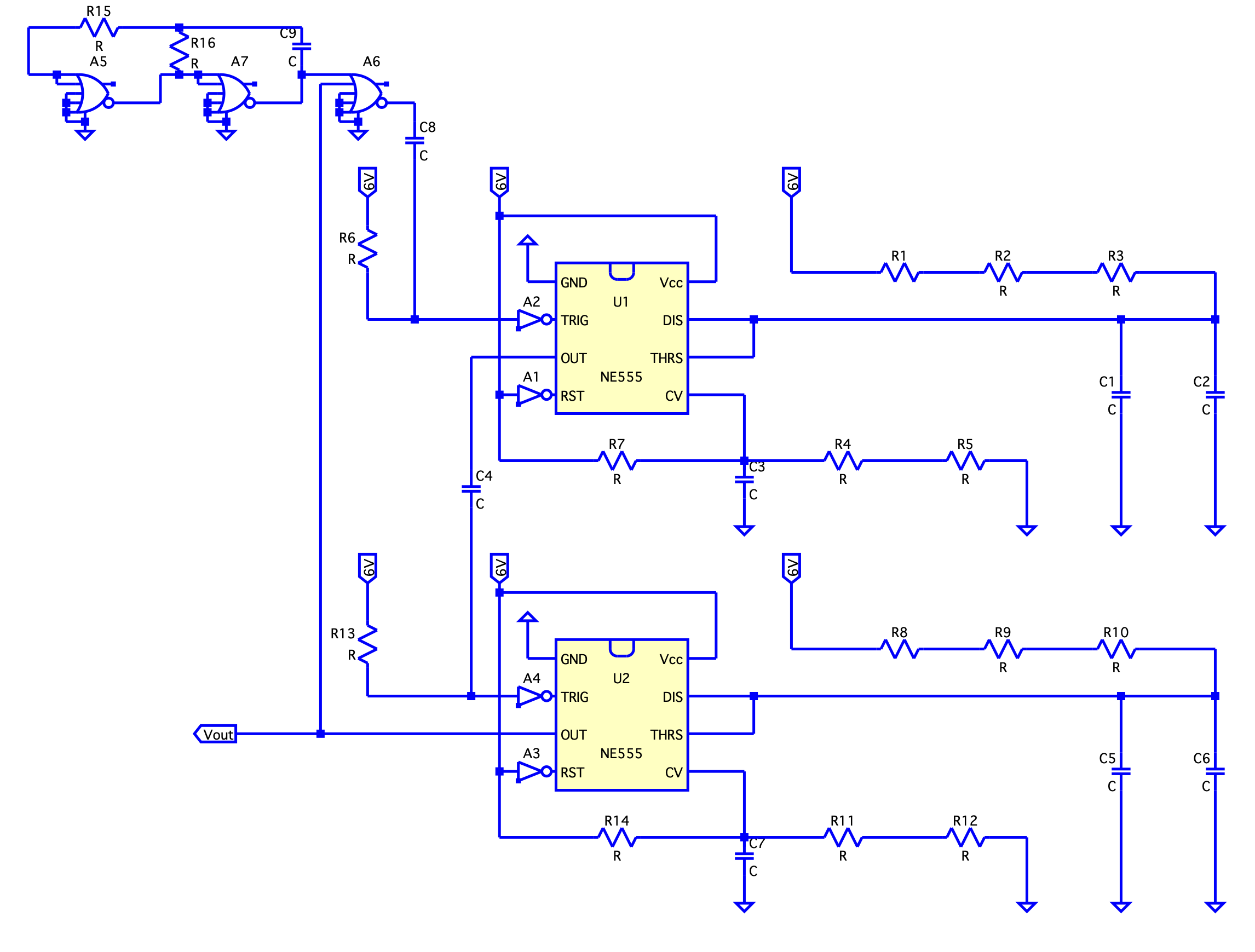
- NOR gates and RC charge/discharge creates \(60Hz\) Pulses
It generates a self-starting square with frequency depending on the \(RC\) value. The expected measurement is a square wave ranging from \(0V \to 6V\) with frequency of \(50Hz\). The accuracy of the frequency does not change the circuit operation in a significantly as long as it varies fast enough than the pump cycle. (This will be explained later from the feedback-loop design from output of U2 to input of A6)
The square wave is being fed to a capacitor, which as as a differentiator. It produces positive/negative spikes depending on either a rising edge and the falling edge of the square wave.
- 555 Timer monostable oscillator, U1
The monostable oscillator NE555 is triggered by a negative spike (LOW) at pin TRIG. This will set the NE555 to a high and reverse biased the transistor built in the NE555. With the internal transistor reverse-biased, that opens the discharge path of the capacitor at pin DIS and the voltage across the capacitor will build-up. In the process of charging, the NE555 will remain in the set state until the capactor charge up to the threshold voltage and reverts its state to the reset state and wait for the next negative spike to be felt for the cycle to repeat.
- 555 Timer monostable oscillator, U2
The bottom 555 timer, which does the exact same things as its counterpart, produce a complementary output from the top 555 timer. Functionally, the pump cannot be ON and OFF at the same time. To achieve this complementary of ON and OFF state, the output of the top 555 timer is connected to the TRIG pin of the bottom 555 timer. When OFF state is over, a negative spike will then be sent to TRIG pin to activate the ON pump signal, with a different time constant \(CR\) preset by the user. This ensures the ON cycle only begins when the OFF cycle ends.
- Feedback from U2 to A6
However, there is a subtlty. Remember that the NOR gates are a self-oscillating circuit that in effect constantly producing the negative spike to trigger the SET state of U1. That suggests U1 will be reverted as soon as it finish the charging cycle (RESET state). But in the same time, we know that U1 and U2 must be complementary in their outputs. It must follow that while U2 in its SET state, U1 must be remained in its PRESET state. To this end, we must suppress NOR gates trigger when U2 at the SET state. The feedback loop from U2 OUT to A6 achieve exactly that. With U2 in its set state, it produces a HIGH on its OUT. Hence, a HIGH is also felt at A6. No matter what input felt at the other pin of A6, it will always produce a LOW because its NOR gate property. The self-oscillating character is then suppresed by the feedback loop from U2.
Simple logic control
The TimingCycle signal, in the form of timed square wave, is sent to the SimpleLogiclControl. The SimpleLogiclControl will coordinate the activation of the Bleed Solenoid, Dump Solenoid and the vaccum pump according to the timed square wave.
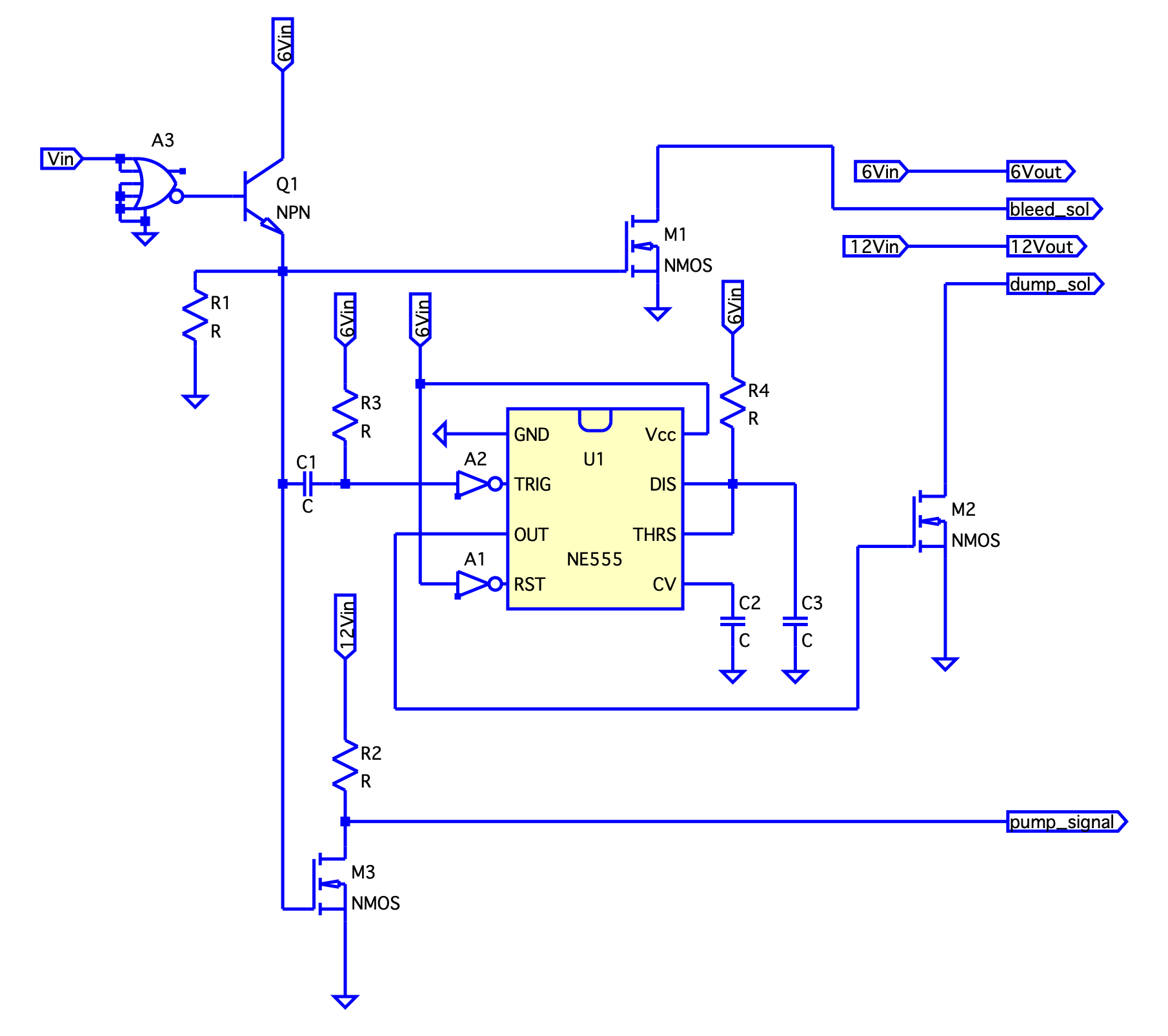
- Input voltage controls the state of Q1, which in turns changing the state of M1, M3 and U1
With a LOW at its input, the NOR gate will revert it to a HIGH, forward biasing Q1. This creates a voltage drop across R1 and forward biasing both M3 and M1.
Changing to a HIGH at its input will produce a LOW at Q1 base, reverse biasing Q1. The transition will be felt by C1 which produces a negative spike to put U1 into a set state. Meanwhile, both M1 and M3 will be reverse biased.
- M3 sends the pump signal to switching power regulator, activating or deactivating the pump
If a LOW in the SimpleLogicControl input, M3 will be forward biased, bring the pump signal to ground producing a LOW and turning the pump ON.
Whereas a HIGH in the SimpleLogicControl input will turn the pump OFF. Further details will be elaborated in the Pump Drive section. For the time being, it is important to know the pump’s states correspondence with the inputs.
- M1 controls the bleed solenoid
With a LOW input, A3 reverts it to HIGH which forward biased Q1. Subsequently, M1 will be forward-biased, bring bleed_sol to ground and create a voltage difference to energize the bleed solenoid. Hence, the bleed solenoid will align with the pump state to regulate the pressure; when the pump is ON, the bleed solenoid is also On. When the pump is OFF the bleed solenoid is also OFF.
- U1 controls the dump solenoid
The U1 is only triggered by a negative spike induced from a transition from LOW to HIGH input signal. With U1 put to a SET state, it will output a HIGH for a preset amount of time based on the time constant \(CR\) value. The high output will forward-biased Q3 and creates a voltage drop across the dump solenoid and energizing it. In the functional aspect, whenever the vaccum pump transition from a ON state to its OFF state at its intermittent cycle, the dump value opens up to equalized the pressure.
Pump drive (Switching Voltage Regulator)
The purpose of the pump drive circuit is to accommodate the needs for a stable and efficient source of power to the portable suction unit. Although power regulation can be done simply from the a linear power regulation device, just as the PowerRegulator shown in the System Architecture. But a linear regulator dissipates a lot of heat, which is not desirable in a portable device. An alternative design, the Switching Voltage Regulator, is being used in the unit to increase power efficiency. For a proof of the power efficiency, consult the following article:
( Citation: Keim, 2023 Keim, R. (2023). Closed-loop control for an LTspice switching regulator. All About Circuits Technical Article. Retrieved from https://www.allaboutcircuits.com/technical-articles/closed-loop-control-for-an-ltspice-switching-regulator/ )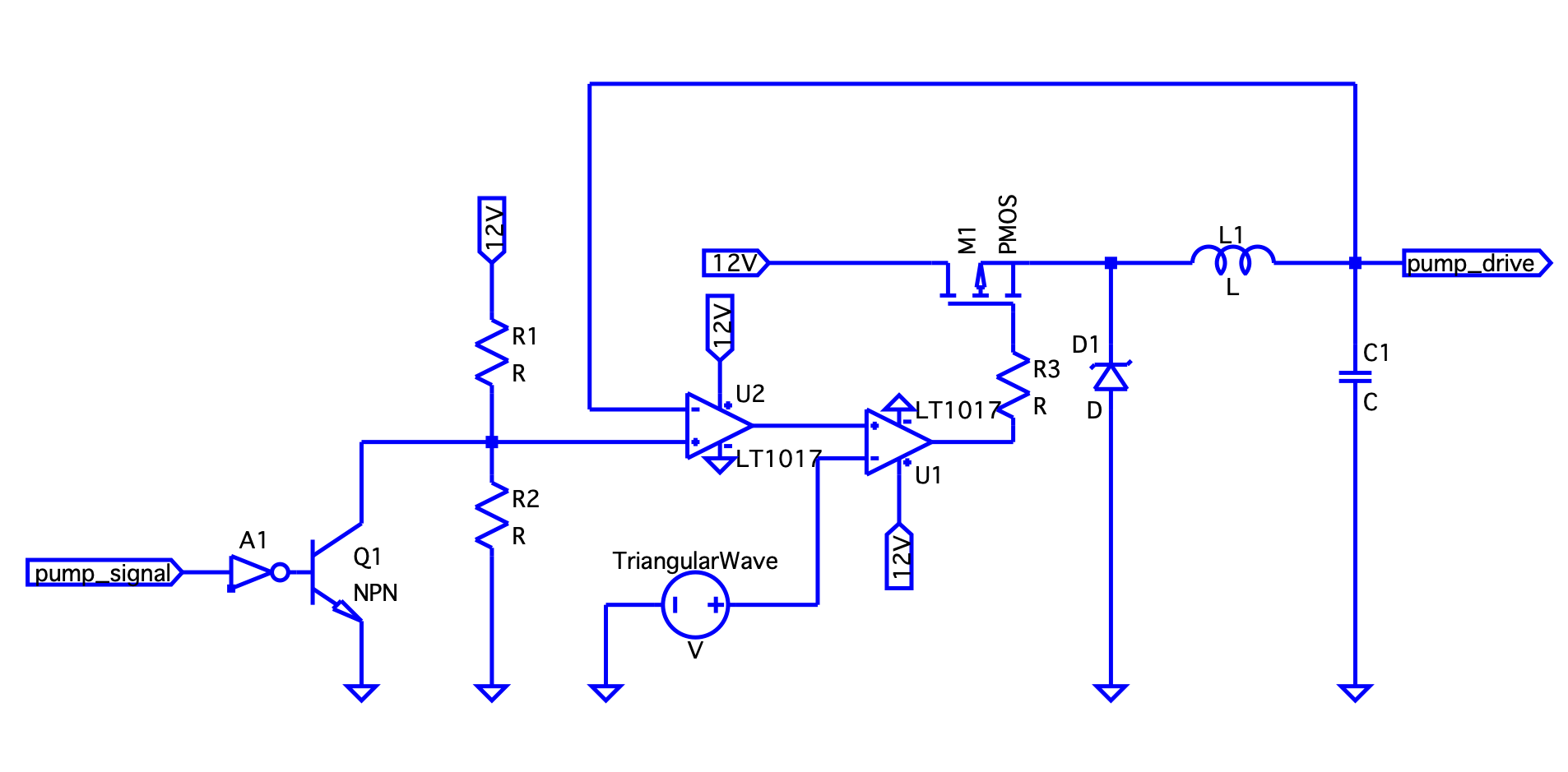
- Switching voltage regulator
The general idea of a switching voltage regulator is to store the energy of the input DC power in the inductor. However, the inductor and capacitor store their energy in the form of oscillating voltage and current, but not DC. So, one also has to convert the DC into oscillating waves. In additionally, the AC signal has to be converted back to a control output DC signal. The Switching Voltage Regulator must incorporate design with these two restriction.
To break down the circuit design shown above, we group U1 and U2, PMOS, inductor and capacitor and dideo into their functionalities. U1 and U2 are used to produce a voltage controlled Pulse Width Modulation (PWM) from the voltage divider R1 and R2. The PWM is then used to switch the PMOS transistor ON and OFF to produce a square wave with varying duty cyle from PWM. The oscillating current is felt across inductor L1 where energy can be stored. Lastly, the diode and the capacitor is being used to produce a rectify and smooth DC output signal, with its magnitude controlled by the PWM.
- Mechanism
With a LOW input pump_signal, the inverter A1 put it to a HIGH which forward biased Q1 forcing the voltage at the comparator U2(+) to be low. A LOW is then felt at U1(+) result in absence of voltage at the gate of M1. The 12V is then unable to feed the vaccum pump.
With a HIGH input pump_signal, Q1 will be reverse-biased, the designed voltage will be felt at the comparator U2(+). The positive input of U2 will then be compare with the feedback signal at the negative input of U2 to send the error signal to the comparator U1 forming a negative feedback loop. The larger the difference from ideal voltage, the larger the adjustment till it reaches its optimal design-value. U1 will then produced a control square wave with destinated duty cycle. The duty cycle is proportional to the output voltage and ideally a controlled 6V DC will be produced to drive the pump.
The mechanism incorporates feedback loop to stablized output, with the trade-off for being more complicated in design and higher built-cost. The Switching voltage regulator runs at a \(90 \% \) efficiency, which outweighs the downside in a portable design.
Troubleshooting Considerations
Understanding the mechanism at a smaller and component level, will allow us to troubleshoot down to a smaller and relevent level. In a practical setting, equipment faults are generally spotted by two cases:
The unit is in operation and it fails to perform
During calibration test where the value is off from the accepted value
Half-way troubleshooting
Some troubleshooting scenarios will be proposed. Some helpful tips of troubleshooting is the Half-way troubleshooting, which comes in handy if one could trace from the source to the symtom.
For example, if from mid-way the measurement is off from the expected reading, then we trace up to the source by locating another half-way between. If the mid-way measurement is good, then we trace down to the symtom half-way to locate the actual bug. This method will be demonstraed in the following scenario.
Example Symtoms and troubleshooting suggestions
- Scenario 1: Pump not energized
Check if the pump works under continuous mode. If continuous mode works, then troubleshoot the intermittent mode. First, we identify the source to the symtom, which is from 12V to 6V, TimingCircuit, SimpleLogicControl to send pump control signal, and lastly Pump control signal to pump drive power. A good point to start is from the SimpleLogicControl to see if Q1 is producing the correct output. If it is reading false output, then we can trace it to the TimingCircuit. If not, we can trace it to the PumpDrive.
- Scenario 2: Off-reading pressure calibration failure
In this case, the pressure reading is off from the designed value with a working pump. We know the vaccum/pressure regulation is done by the bleed solenoid and the dump solenoid. So, we identify the following flow from source to symptom: 12V/6V, Timing Circuit, SimpleLogicControl, Bleed Solenoid or Dump Solenoid. Again, we will start from mid-way, Q1 in SimpleLogicControl block. Then, either to trace it back to the timing circuit or M1 for bleed_sol or M2 to dump_sol.
- Scenario 3: Intermittent mode time calibration failure
If only the timing of the pump operation is off from the preset value, but all the other components work as expected, then it must be a faulty TimingCircuit. We identify the flow: NOR gates oscillator, U1 NE555, U2 NE555, SimpleLogicControl and lastly to the PumpDrive. One can further narrow it down if either the pump has a faulty OFF time or a fault ON time. We know U1 produce the ON time signal whereas U2 produce the OFF time signal.
Conclusion
Although the Zoll 326M suction pump has reached end-of-service life, its architecture presents a clear and instructive example of analog medical device design. By decomposing the system from functional behavior to circuit-level implementation, we observe how timing logic, actuator control, and power regulation integrate to ensure safe and reliable suction performance.
The coordination between the vacuum pump, bleed solenoid, and dump solenoid illustrates a practical hybrid control system combining mechanical dynamics with discrete logic timing. Through systematic block-level reasoning, troubleshooting becomes a structured process rather than component replacement by trial.
Studying legacy systems such as the 326M strengthens both engineering intuition and diagnostic discipline. Understanding how power flows, signals propagate, and feedback stabilizes behavior provides insight not only for maintenance, but also for the design of future biomedical systems.
In this sense, the 326M serves not merely as an obsolete device, but as a compact laboratory for applied control theory, power electronics, and system-level medical engineering.
Bibliography
- (1995)
- (1995). Model 326M series suction unit: Instruction manual. Impact Instrumentation, Inc..
- Shirriff (2016)
- Shirriff, K.(2016, 2/20). Retrieved from https://www.righto.com/2016/02/555-timer-teardown-inside-worlds-most.html
- Keim (2023)
- Keim, R. (2023). Closed-loop control for an LTspice switching regulator. All About Circuits Technical Article. Retrieved from https://www.allaboutcircuits.com/technical-articles/closed-loop-control-for-an-ltspice-switching-regulator/
- (2007)
- (2007). Ultra-lite model 326 intermittent aspirator. Retrieved from https://respiratory-therapy.com/miscellaneous/ultra-litetrade-model-326-intermittent-aspirator/?utm_source=chatgpt.com